Page 2 of 3
Re: Decrypting Bravia Firmware BIN File
Posted: Sun Oct 16, 2011 2:11 am
by erdem_ua
Friend Burak work hard on it. I wish to help little but no idea...
But I noticed the ` Widget Development Kit`
Does TV supports widgets? Specially custom ones...
Than build a widget that opens a telnet socket. You are in...
I don't know about JTAG, of if could it revive my board bricked 2 days ago.
Probably gonna buy new board.
Re: Decrypting Bravia Firmware BIN File
Posted: Sun Oct 16, 2011 2:22 am
by coolrecep
Actually JTAG can revive your board and I have the SPI flasher that will probably work for you if the board have JTAG port.
On the other hand, Widgets must be sent to Yahoo and then signed etc etc... I don't think the TV is goig to accept widgets right away...
BTW, if you can, please investigate the packets:
http://openlgtv.org.ru/forum/viewtopic.php?p=2268#p2268
I have also found the service menu. I will check it out

Re: Decrypting Bravia Firmware BIN File
Posted: Sun Oct 16, 2011 6:18 am
by erdem_ua
SPI? SPI is different protocol than JTAG. So It won't work.
Just need someone that understands from JTAGing. Also JTAG changes for chips. So one JTAG solution doesn't fit all.
You needed to identify chips and it's addresses etc...
Re: Decrypting Bravia Firmware BIN File
Posted: Sun Oct 16, 2011 11:53 am
by coolrecep
You may be right. There is also chance for buying nand flasher, removing them, flashing and then soldering back.
BTW, SPI flasher is used for XBOX360 JTAG flashing.
BTW, I have bought the serice manuals
40 $ but it's woth
Finally I think I got someting:
UART0_TXD/RXD
UART1_TXD/RXD
DEBUG I/F
Re: Decrypting Bravia Firmware BIN File
Posted: Wed Oct 19, 2011 11:45 pm
by coolrecep
Got new info!
The file is %100 encrypted with one of the below algos:
AES, Multi2, DVB, DES and 3DES functions
So, could you take a look at it again or could you help me how to handle it?
Thanks.
Re: Decrypting Bravia Firmware BIN File
Posted: Thu Oct 20, 2011 12:41 am
by erdem_ua
It doesn't matter since you don't know the secret key, right? Why do you still wanted to try drill hole at the wall? Just enter from the door...
Since you pointed RS232 port, you can access the shell and dump the unencrypted flash partitions to your USB Flash....
Re: Decrypting Bravia Firmware BIN File
Posted: Thu Oct 20, 2011 11:53 am
by coolrecep
It is 10 port, RS232 is 9 port. Could you please take a look at the port and tell me if it is out of the standard or not?
Page 82, right side, search for CN2403 in PDF.
http://www.scribd.com/doc/69020198/Serv ... DL-52LX900
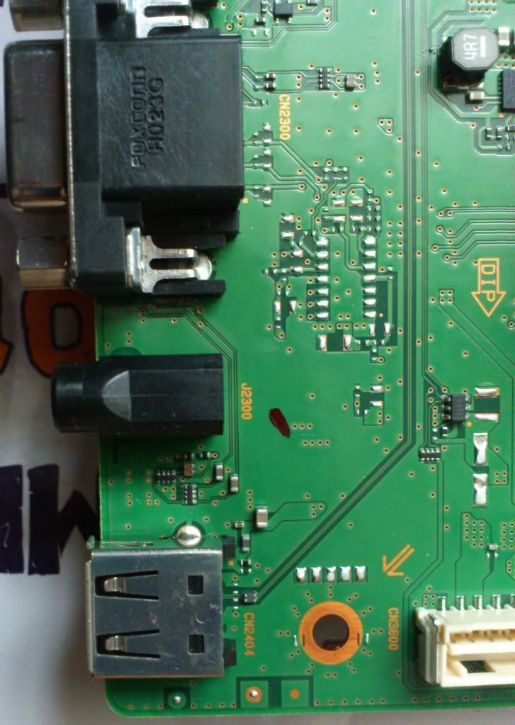
Also right under that schematics there is Right Angle (DIP). I can not understand what is it used for. Maybe it is the switch that enables USB debug port? The picture of this DIP can be found here also, very close to USB port:
http://i1085.photobucket.com/albums/j42 ... C_0039.jpg
Re: Decrypting Bravia Firmware BIN File
Posted: Thu Oct 20, 2011 11:28 pm
by erdem_ua
9 port? Do you sure that what you are searching?

In page 82, there is no RS232 at available on top right connector... And I can say, device has more than one RS port...
One of it for TV tuner... Other for debug. Also some other com port could be in device. All you needed to find is DEBUG IF connector. That's all.
But you look likely gonna bricking your Sony by searching 9 pin port at MB...
Re: Decrypting Bravia Firmware BIN File
Posted: Fri Oct 21, 2011 12:35 pm
by sbav1
Nice service manual, with actual schematics included! I wish post-2009 Samsung TV service manuals were that detailed..
Connector you are looking for is probably CN5502 (18pin, should be under CI/CI+ slot, on solder-side, see page 100).
There are at least 3 different serial ports on that connector. Those are (most likely) TTL-level serial ports with 3.3V signaling.
For that task, you will need "RS232 to 3.3V TTL Converter" (e.g.: MAX3232 based, 3.3V variant).
Re: Decrypting Bravia Firmware BIN File
Posted: Fri Oct 21, 2011 3:59 pm
by coolrecep
Thanks for the reply sbav1, what about this one:
U_RS232_RXD
U_RS232_TXD
Pin numbers 96 and 97 on page 88. Connector name CN5000, chip name IC5000.
Look at that picture I have taken:
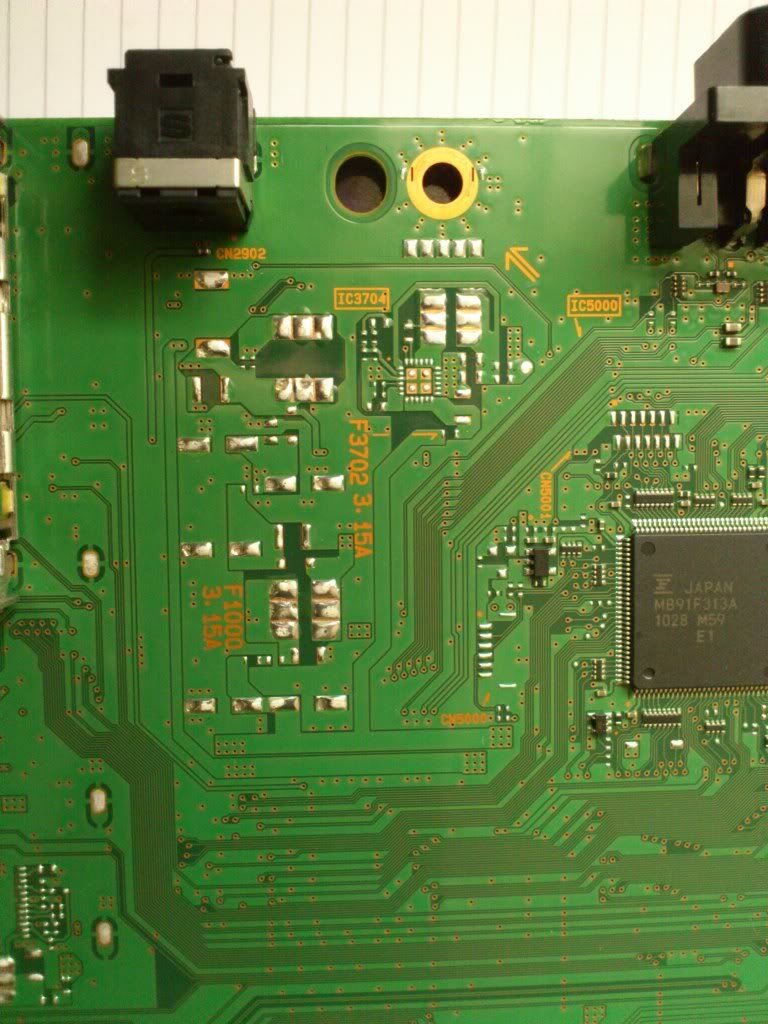
You can clearly see the 6 solders left side of the chip. Two of them have trace. Those two traces are U_RS232_RXD and U_RS232_TXD, enoguh to get RS232 to work. Now it says 3.3V standby. I think I need to keep the TV in standby mode so that the board will have enoguh current for the rs232 port and the chips to operate.
Now the weekend is coming, I need to attack on the right port. BTW, the TV has to be in the stand by mode right? I don't want to fry anything
//I have two JTAG experience with XBOX 360. All good.
P.S. I paid 40 bucks for those manuals