So there is one more Samsung TV which clicks and refuses to power up. When connected to mains, the red Standby LED lights up. When trying to turn the TV on, it clicks, tries to turn on, the LED starts flashing and after 4-5 seconds it turns itself off, clicks again, after which it tries to start again and this loop goes on forever. Everything was all stock (not rooted, no tampering with the firmware) before it went bad.
TV Model: UE40C6000RWXXH
Power Supply: BN44-00357A
Mainboard: BN41-01444B
The power supply is working properly (all voltages appear to be normal) and I can turn on the backlight. I thing that the issue is in the mainboard, so I started investigating and I noticed that the EEPROM chip has voltage on all pins on the one side and no voltage on the other side:
S24CS0 2AVK4 K670
Is this normal? Could this be the reason the TV won't start?
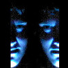
On more thing - while the clicking goes on and on, I noticed that the red chips get warm and the green one stays cool:
The one that remains cool is IC8001 - SDP 91. Is there any way I could verify if this is the problem? Thank you
Samsung UE40C6000RWXXH - clicking, won't turn on, EEPROM issue?
- beatfreak
- SamyGO Project Donor
- Posts: 591
- Joined: Tue Aug 23, 2011 9:03 am
- Location: Hamburg
- Contact:
Re: Samsung UE40C6000RWXXH - clicking, won't turn on, EEPROM issue?
the large copper areas are usually on ground/0V potential, on your pic you can see that your "pins without voltage" are connected to 0V,
you would need an oscilloscope to check wether serial data is going in and/or out the eeprom
a quick search for s24cs0 brings up a datasheet that explains at least the all-ground-side of the chip, the yellow marker indicating pin1 being an address input (as well as pin 2 and 3) theyre all connected to GND to set an adress of 0, pin 4 is the actual GND connection for Voltage supply
//UE40C6500 @ T-VALDEUC 3011 // rooted manual HotelMode style // PVR to NFS via 18MB on-the-fly sparse XFS //
FYI: you can close your ssh session with SamyGO with
If you can't fix it using dvct tape, you are not using enough dvct tape.
FYI: you can close your ssh session with SamyGO with
Code: Select all
~.