Save/Restore config eeprom

Samsung's BluRay player related hacks.

oga83
Posts: 268
Joined: Sun Mar 18, 2012 10:11 pm
Location: France

Save/Restore config eeprom

Post by oga83 »

I modified the Arduino interface project (IR generator + debug console by telnet) so that it can also save/restore the config eeprom (http://wiki.samygo.tv/index.php5/Ethern ... _Interface)

I hope it will allow config backup for later easy unbrick, or maybe allow config modification that we cannot do with the setup menu (enable visual test for example).

Decoding the config is not obvious. If some parameters are easy to locate (pin code for example), most of them are not.

Code: Select all

0038B0h   01 0F 0F 0F 0F 0F 0F 01 01 02 00 61 00 61 00 61   ...........a.a.a
0038C0h   00 61 00 61 00 61 00 00 00 00 31 32 33 34 01 01   .a.a.a....1234..
0038D0h   E5 00 00 00 00 00 00 00 00 00 00 00 00 00 00 00   ................
At this point, it can only save the config, not restore it :
I'm very carefull in my writing tests, and until now, my device eeprom is read only; I think the WP line is directly connected to the processor and cannot be forced low (like SDA or SCK), but I'm still investigating on this.
User avatar
juusso
SamyGO Moderator
Posts: 10129
Joined: Sun Mar 07, 2010 6:20 pm

Re: Save/Restore config eeprom

Post by juusso »

OMG, sounds promising! Don`t stop please :)
Now we also have chance to unbrick TV by resetting eeprom in hard way, but your approach is much better. The only con is - develop board (arduino...) is needed... Anyway, waiting for success on writing back to eeprom ;)
LE40B653T5W,UE40D6750,UE65Q8C
Have questions? Read SamyGO Wiki, Search on forum first!
FFB (v0.8), FFB for CI+ . Get root on: C series, D series, E series, F series, H series. rooting K series, exeDSP/exeTV patches[C/D/E/F/H]

DO NOT EVER INSTALL FIRMWARE UPGRADE
oga83
Posts: 268
Joined: Sun Mar 18, 2012 10:11 pm
Location: France

Re: Save/Restore config eeprom

Post by oga83 »

juuso wrote:The only con is - develop board (arduino...) is needed...
I agree, but on the other hand, Arduino Ethernet board is less than 50$ and burning the sketch into the board is easy (you can use your exlink cable for this :) )
Moreover if your TV/BD pcb has I2C test holes (like the bd-e8300 on the following photo), no soldering is required with the use of stiff wires
Image

We could also easily use a PC printer port (instead of Arduino) but at this point, using Arduino is easier for me as the board is all-in-one : Sending IR code, Debug console, and Eeprom reading , all by network :)
We can do this later when the concept is validated !
User avatar
juusso
SamyGO Moderator
Posts: 10129
Joined: Sun Mar 07, 2010 6:20 pm

Re: Save/Restore config eeprom

Post by juusso »

yes, I2C test holes present on D series arm models, not only BD players ^^
LE40B653T5W,UE40D6750,UE65Q8C
Have questions? Read SamyGO Wiki, Search on forum first!
FFB (v0.8), FFB for CI+ . Get root on: C series, D series, E series, F series, H series. rooting K series, exeDSP/exeTV patches[C/D/E/F/H]

DO NOT EVER INSTALL FIRMWARE UPGRADE
oga83
Posts: 268
Joined: Sun Mar 18, 2012 10:11 pm
Location: France

Re: Save/Restore config eeprom

Post by oga83 »

I was able to write in the eeprom :)

Code: Select all

#URL to read the first 128 bytes
http://172.17.10.253/read?format=0&device=80&size=128&addr=0

0000: FF FF FF FF FF FF FF FF FF FF FF FF FF FF FF FF FF FF FF FF FF FF FF FF FF FF FF FF FF FF FF FF ................................
0020: FF FF FF FF FF FF FF FF FF FF FF FF FF FF FF FF FF FF FF FF FF FF FF FF FF FF FF FF FF FF FF FF ................................
0040: FF FF FF FF FF FF FF FF FF FF FF FF FF FF FF FF FF FF FF FF FF FF FF FF FF FF FF FF FF FF FF FF ................................
0060: FF FF FF FF FF FF FF FF FF FF FF FF FF FF FF FF FF FF FF FF FF FF FF FF FF FF FF FF FF FF FF FF ................................

# URL to write 41 at @0x20
http://172.17.10.253/write?device=80&addr=20&data=41

#URL to read the first 128 bytes
http://172.17.10.253/read?format=0&device=80&size=128&addr=0

0000: FF FF FF FF FF FF FF FF FF FF FF FF FF FF FF FF FF FF FF FF FF FF FF FF FF FF FF FF FF FF FF FF ................................
0020: 41 FF FF FF FF FF FF FF FF FF FF FF FF FF FF FF FF FF FF FF FF FF FF FF FF FF FF FF FF FF FF FF A...............................
0040: FF FF FF FF FF FF FF FF FF FF FF FF FF FF FF FF FF FF FF FF FF FF FF FF FF FF FF FF FF FF FF FF ................................
0060: FF FF FF FF FF FF FF FF FF FF FF FF FF FF FF FF FF FF FF FF FF FF FF FF FF FF FF FF FF FF FF FF ................................

# URL to write back FF
http://172.17.10.253/write?device=80&addr=20&data=41
To do that, I just connected WP to GND. BUT, I did that directly on the chip, not on the connector holes.
The signal WP on the connector is connected :
1- directly to the ARM, with a 4.7k pull-up to VCC
2- to the 24512 througth a 39 ohms resistor
As there is a 4.7k pull-up on this line, we can think that the output on the ARM is an open collector one; thus it would be safe to force it to GND, but I have no proof of that, and I don't wan't to burn it ;)
And I don't explain why they placed a 39ohms resistor between, except to be able to force WP to GND directly on the chip without sinking to much current from the ARM if it's is not an open collector...
[EDIT] I also tried to force the WP-hole to GND through a 100 ohms resistor without any success : the ARM output is stronger which means that it's not an open connector...
Anyway, it is not so complicated to do so. When I'll feel more confident, I'll try to use the WP hole...
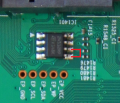
How to proceed :
- Power up you TV/BD, and wait for the boot to be complete
- Connect SDA hole to Arduino A4 with a 100 ohm resistor
- Connect SCK hole to Arduino A5 with a 100 ohm resistor
- Connect GND hole to Arduino GND
- Connect 24512 pin 7 to GND
- Issue the arduino embedded web server URLs to read or write the eeprom
I2C.png
Don't think about reading the eeprom while the BD/TV is powered off... You cannot provide 5v-power to eeprom with the 5v-hole because it is also connected to many other chips, and the SDA,SCK lines are grounded by the ARM it is off.
It is safe to access the eeprom when the unit is on, because :
- There is an eeprom cache in exeDSP. Whenever, the software needs a config param, it will read it from the cache (except at boot time); So, most of the time, the eeprom is not used.
- The 100 ohms resistors on SDA and SCK allow the ARM to use the eeprom even if Arduino is connected; But don't try to access the eeprom while modifiyng the config on your tv/bd ;)

Currently, the Arduino sketch is able to read the whole eeprom at once, but it can only write one single byte for each command. I'll modify it to be able to write the whole eeprom at once later (at least when my unit will be bricked !)
You do not have the required permissions to view the files attached to this post.
User avatar
juusso
SamyGO Moderator
Posts: 10129
Joined: Sun Mar 07, 2010 6:20 pm

Re: Save/Restore config eeprom

Post by juusso »

as i said, this is great finding!
if you find where to change eeprom to switch between active partitions (toggle command writes some data to eeprom to let TV know which active partition to boot)
also might this possible to use exlink for this goal...? :)
LE40B653T5W,UE40D6750,UE65Q8C
Have questions? Read SamyGO Wiki, Search on forum first!
FFB (v0.8), FFB for CI+ . Get root on: C series, D series, E series, F series, H series. rooting K series, exeDSP/exeTV patches[C/D/E/F/H]

DO NOT EVER INSTALL FIRMWARE UPGRADE
oga83
Posts: 268
Joined: Sun Mar 18, 2012 10:11 pm
Location: France

Re: Save/Restore config eeprom

Post by oga83 »

Yes, you can read the eeprom with TDM :

Code: Select all

20102011
20089999
11
2
0
==============================
 [ TDsEEPROMStore Debug Menu ]
------------------------------
 0x01  : Create
 0x02  : Destroy
 0x03  : FlagCreate
 0x04  : Read
 0x05  : Write
 0x06  : Physical Read
 0x07  : Physical Write
 0x08  : Nvram Fill Data
 0x09  : Nvram Crash Verify
 0x10  : Physical Read loop
 0x11  : Nvram reset
------------------------------
 0x99  : Exit Debug
------------------------------
TDStore>: 0x6
Start Address <<: 0x0
Length <<: 0xFFFF

NVRAM Read End 0 Time
Read data[0] = 0xff
Read data[1] = 0xff
Read data[2] = 0xff
...
...
Read data[65534] = 0x0
If you paste the result to the file 'eeprom.txt', you can easily convert it to a binary file :

Code: Select all

echo -n -e $(cat eeprom.txt | grep "^Read data" | tr -d '\r' | awk '{ print substr("00" substr($4,3), length($4)-1) }' | tr -d '[:space:]' | sed 's/../\\x&/g') >eeprom.bin
However, some portions are not the same that what is read with I2C (147 bytes in the middle and 128 bytes at the end) :( . I will investigate on this.
[EDIT] In fact, only around 60 bytes are different + the last 128 bytes. The files have not been captured at the same time : this could explain the 1st difference; For the 2nd one, it seems that the last 128 bytes are not used and TDM returns 0 from its cache - If we use TDM 'physical read' (0x6 instead of 0x4 - I also edited the TDM commands above), it returns the same 0xff value than I2C !)

Of course, you can use TDM to restore the eeprom. The following code will generate the TDM commands (to paste in putty), once you are in the "TDsEEPROMStore Debug Menu" menu :

Code: Select all

od -w1 -v -t x1 -Ax eeprom.bin | awk '{ print "7\n" substr($1,length($1)-3) "\n1\n" $2 "\n" }'
This allow easy eeprom backup/restore (only exlink is required) :)
Arduino would be reserved to restore devices bricked so far that TDM doesn't work anymore !
sbav1
Official SamyGO Developer
Posts: 374
Joined: Fri Jan 15, 2010 10:20 am

Re: Save/Restore config eeprom

Post by sbav1 »

juuso wrote:as i said, this is great finding!
if you find where to change eeprom to switch between active partitions (toggle command writes some data to eeprom to let TV know which active partition to boot)
I think this particular setting (kernel partition toggle/select) is most likely stored in the different EEPROM (connected to sub-micom - usually a small one, 256bytes or 512 bytes).
BTW, there should be some track on the mainboard between main SoC (GPIO pin) and sub-micom (also GPIO pin) which are used for that purpose.
Assuming we can force this track up/low (I expect this track to be equipped with some kind of test pad or something) we should be able to select kernel partition we want to boot.
also might this possible to use exlink for this goal...? :)
I think toggle command doesn't write anything to any EEPROM directly; it's done by issuing a specific command[s] to sub-micom (generally via /dev/ttyS* - on TVs, or via /dev/spi* - on some BD player models). Sub-micom EEPROM is not directly connected to main SoC, so "TDsEEPROMStore Debug Menu" in TDM most likely can't be used for partition switch.

But, there may be a way to toggle partitions using TDM (by some different debug menu related to MICOM, perhaps).
sbav1
Official SamyGO Developer
Posts: 374
Joined: Fri Jan 15, 2010 10:20 am

Re: Save/Restore config eeprom

Post by sbav1 »

Well done, congratulations!

I think this is Samsung vanilla general-purpose IO pin (probably quite similar to the GPIOs they use in their ARM developement board SoCs, eg. S3C2440 or S36410 to name a few).
They are configurable (by pad control registers) as inputs/outputs, with or without internal pull up/pull down resistors enabled etc.
oga83 wrote: As there is a 4.7k pull-up on this line, we can think that the output on the ARM is an open collector one;
External 4.7k pull-up is probably there to ensure EEPROM is write protected even before the pins are configured properly on boot time.
Question is - do they have internal overcurrent protection? I dunno.. From the experiments with my spare B650 mainboard, I found them (reasonably) abusable. E.g., I misconfigured pad control registers (many times, switching inputs to outputs etc.). I've shorted one GPIO pin once to GND, for about 20 seconds (configured as output, in high state, no current-limiting resistor involved as far as I can tell) - just by mistake, I forgot to switch multimeter from A to V :oops: Measured current was ca 20mA, AFAIRC. So far, no apparent damage ;).
oga83
Posts: 268
Joined: Sun Mar 18, 2012 10:11 pm
Location: France

Re: Save/Restore config eeprom

Post by oga83 »

Thanks !

Yes, there is another eeprom :
When I was looking for the code that decodes IR frames on my BD, I investigated in Micom and its Renesas 78K0/Kxx microcontroller.
It also has a 2k-bits I2C eeprom (S24CS02), and a serial ttl line (that lead to a connector footprint) but there is no prompt in it...
I can try to read this eeprom; I'm pretty sure we cannot do this with TDM
Is there a way to trigger the partition swap ? If yes, we could read before and after to see what has changed

Apart of the front pannel (and maybe the power on/off system), do you know what is exactly doing Micom ?
Do you have an image of the Micom software that is downloaded into the Renesas ?

About pull-up and boot time, most of these eeproms have a delay to prevent spurious write during power up
About the processor (SDP1105), it quite impossible to get information on it (probably submitted to NDA) :(

Post Reply

Return to “BluRay Players”